Friday, December 7, 2012

Interview with Two Riggers


This interview is with a rigging student at the University of Texas at Dallas named Micheal. 


1.   Why do you like rigging?

      I am a huge fan of anatomy and rather good at math; and that sort of transferred into the rigging field. It helped me place the joints in more proper areas and understand the technical aspects of rigging.

2. How would you compare rigging to other aspects of animation?

    Rigging is very technical compared to other aspects of animation. There's constraints and scripting involved which the other areas never touch. Usually the most often thing to 'break' in an animation is a character rig because of the technical mumbo jumbo. In the end though, rigging is a must or else the characters can't move. We are nothing without our bones!

3.  What has been your greatest struggle in rigging?

     My greatest struggle in rigging is fixing problems when they arise. Sometimes it can be simple like de-parenting or removing a constraint. Other times it involves more work, and hopefully not an entirely new joint set-up.

4. What part do you enjoy the most?

     I enjoy the laying out of the joints and the skinning process the most. The laying out of joints involve lots of pre-thought and that makes it all the more exciting. The skinning is when you bind the bones to the skin. It makes me feel like Dr. Frankenstein reanimating a corpse!

5.  What advice would you give to someone starting out in rigging?

     The biggest advice I could give is to not give up. Rigging is a trial and error process. There is more than one way to skin a model (literally). Problems will happen, learn from them and keep moving forward.
 

 This is an interview with Professor Farrar from the University of Texas at Dallas.


1. What areas of rigging do you see students struggle with the most?


        Rotation order -- Understanding how rotational values of objects stack up on top of each other is probably one of the trickiest concepts for students to get their heads wrapped around.  Using spline IK in character spines is also an area that a lot of students struggle with.

 2. How would you describe your experiences in the industry as a rigger?


        Constantly learning -- Not only did I have to learn new software and rigging techniques when working in the industry, but also because of the complexity and detail involved in the types of characters we were rigging, I was constantly learning about human and animal anatomy.

 3. What has been your greatest struggle in rigging?


        Staying current on all the new versions of software that come out.  The basic fundamentals mostly stay the same, but there are constantly new tools being developed and it's difficult to gain expertise is all of them.

  4. What do you enjoy the most about rigging?


        Problem solving!  Figuring out why a rig is broken or isn't working like it's supposed to and/or coming up with new, elegant solutions to some technical problem that is best solved with a rig.

 5. What is the best tip for someone looking into rigging, but unsure about committing to it?


        Really pay attention to the details and try to understand as much as you can about why things are behaving the way that are.  Don't just use the excuse of "Maya did this to me..." or "IK handles don't really work for me..." (I hear that kind of stuff all the time).  Instead, take the time to figure out exactly what's going on "behind the scenes" with whatever particular tool you're trying to understand.  The better you understand how a tool or rigging feature works, the easier it is to apply it to some unique problem-solving situation.

Tuesday, December 4, 2012

Rigging Programs

Rigging Programs
 

            Hello there, Beginner Riggers! This is CR Rescue pet from myfirstrescuepet.blogspot.com. When I saw Beginner Rigger, I just knew I had to contribute by letting you all know about two great colleges that some of my friends currently attend and love where you can learn more about rigging. Let us know if either of these are your colleges, or perhaps where a friend attends, and what you think.

            Full Sail University, located in fun-loving sunny central Florida, offers courses in basic rigging, character rigging, and in many other areas of digital animation.  Full Sail is dedicated to turning out artists ready to secure competitive and creatively fulfilling positions in the entertainment industry.  As Full Sail’s fast-paced academically rigorous degree programs are set up to help you earn a four year degree in as little as two years, there is little room for failure, and students note that it is difficult to pursue other interests or have an outside job while pursuing a degree at Full Sail. As entertainment related degrees are the only programs offered at Full Sail, and their two year program gets students through quickly with little room for non-major related content, it is an ideal university for riggers who are serious about their studies and certain that they want to be out and rigging professionally as quickly as possible. Notable alumni riggers have been successfully involved in many well-known projects including the Call of Duty videogame series, Pixar films such as Finding Nemo and Ratatouille, and the Harry Potter films.

             Known for small classes and generous financial aid packages and rated one of America’s Best Kept College secrets, Santa Fe University of Art and Design offers a Digital Arts program focused on preparing student artists for the entertainment industry. Their program offers a comprehensive approach, including both 2D animation foundations, as well as photography, along with traditional 3D animation instruction. Santa Fe University of Art and Design hopes that this interdisciplinary approach will help produce well rounded artists as well as competitive career animators. Their Bachelor of Fine Arts in Digital Arts focuses more on creative expression, which can often go neglected. It is truly a fine arts degree you are obtaining, focusing on buildingblocks such as storytelling and illustration. Santa Fe University of Art and Design prides itself on being a school of creative freedom, collaboration, and craftsmanship. The school, however, does not lose sight of the ultimate goal of graduate employment, and therefore offers instruction in web publishing and encourages students to make their work felt in the art-hungry Santa Fe community and marketplace.

References:

Programs. Full Sail University. Retrieved from: http://www.fullsail.edu/
Programs. Santa Fe University. Retrieved from: http://santafeuniversity.edu/

Friday, November 30, 2012

Lesson 6: Laying out Joints and Making IK Handles

Lesson 6: Laying out Joints and Making IK Handles


Laying Out the Joints

              In this video, I demonstrate how to make a set of joints for a humanoid torso.


Making an IK Handle

               I say that I will show you how to  make an IK Handle, but ran out of time. The set up for the wrist is about what you would do for the joints of an arm.


References:

Immel, Brian J.Forward and Inverse Kinematics.N.D.http://www.jawa9000.com/Technical/fk-ik-arm/fk-ik-arm.htm

Thursday, November 29, 2012

Helpful Tip When Using IK Handles


Helpful Tip When Using IK Handles

Keep in Mind

             Knowing when to work with IK Handles will become more important as you learn more rigging techniques. Keep this concept in mind when laying out a characters joints because knowing where you will put your controllers and what type helps to make working faster. Always keep a look out for what is happening around you so you can learn from nature and replicate movements as much as possible.

Friday, November 16, 2012

Lesson 5: Creating Joint Controllers


Lesson 5: Creating Joint Controllers

Controllers:

                Whenever you are making joints, you always want to build controllers so that you are not grabbing the joints directly. You can make one of two types of controllers, Forward Kinematics and Inverse Kinematics.
                Forward Kinematics refers to a system of controllers in which each controller moves one joint. When moving something like an arm would mean that in order to reach a position, you would first rotate the shoulder. Then you would rotate the elbow, and finally the wrist. The controllers are usually made from NURBS Curves, which are much different from Polygon Primitives. "NURBS stands for Non-Uniform Rational B-splines(M5 Design Studio, 2011)." NURBS Curves do not render in Autodesk Maya. They are simple objects and many do not have faces. You want to use either an Orient Constraint or use an Expression, depending on the situation. Forward Kinematics allow for move direct control.
                Inverse Kinematics controllers are created by the IK Handle Tool found under the Skeleton Tab. The IK Handles allow for a set of joints to be controlled by a single controller. If you had that same arm set and you used an IK Handle, you would be able to control the arm at the wrist. You would have a NURBS Curve that controlled the handle using a Point Constraint and an Orient Constraint on the wrist so the hand could rotate properly. There are several types of IK Handles, but describing them would be more in depth than this post can cover.
                When using NURBS Curves as controllers, you want the curve’s X axis to align with the joint’s X axis as you place the controller where the joint is located. The best way to make them align is to first rotate the new curve 90 degrees in the Z axis and freeze the curve’s translations. Then you want to put the curve in a group by going to the Create Tab and find Empty Group. Parent the curve to the group. Use a Parent Constraint with the Maintain Offset turned off with the joint as the driver, and the group as the driven. Once the group is in place, delete the parent constraint. You can find the constraint by going to the Outliner Window and looking for the group. Once you have found the group, you can click on the plus sign to open up the contents of the group. Click the “!” icon and then hit the Delete button on your keyboard. From there you can use the curve to constrain the joint and it will always have a default position.

References:

M5 Design Studio.(2011).NURS Modeling in Maya 3D 2012.http://m5designstudio.com/2011/maya-3d-tutorials/nurbs-modeling/

Friday, November 9, 2012

Lesson 4: Joints


Lesson 4: Joints

Joints:

                Joints in Autodesk Maya allow you to make skeleton like structures. These structures can be used for characters or objects. You first must build the structure separately as joint chains parented together with control structures, and then you bind it to the mesh to make your model move. We will look at how to make joints and some key points to keep in mind in this lesson.
                You make joints using the Joint Tool found under the Skeleton Tab. The Joint Tool will only allow you to make joints right on the grid. If you are in the Perspective view panel, then any joint you make will be on the grid you see in the center. In order to make a joint chain upright or floating in space, you have to switch between you Front view, Side view, and Front view panels. Every joint you make is parented to the one before it. You can always tell which joint is the child because the parent always points to the child joint.
                You might at some point be tempted to freeze the transformations on a joint, but you should not freeze a joint’s translational values. If you freeze the translational values, then it will go to the same place as the parent joint or the World Origin, the center of the grid. You do not want rotational values on a joint, so if you find a point where moving them is necessary, then freeze only the rotational values. You need to rotate a joint directly when you are placing joints in the places you want them, otherwise you want controllers constraining them. Controllers will be discussed in the next lesson.

Making a Joint Chain:

Step 1: Make sure you are in the Animation Menu, and then go to the Skeleton Tabà Joint Tool

Step 2: Find the view you want and create a set of joints

Step 3: If you feel these need to be tweaked, then change their positions to suit your needs

Step 4: Freeze the rotations if you made any


References:

 Athias, Delano.(2010).Building the Skeleton.http://www.digitaltutors.com/11/training.php?vid=19147&autoplay=1

Wednesday, November 7, 2012

Lesson 3: Expressions


Lesson 3: Expressions


Expressions

                Expressions are useful tools in Autodesk Maya to make specific changes to an object. “Expressions are program-like instructions you create to control keyable attributes over time. Expressions can be comprised of mathematical equations, conditional statements, or MEL™ commands (Getting Started in Maya, 2010, 625).” MEL stands for Maya Embedded Language, and it is not hard to learn. The “keyable” attributes are those like translate, rotate, and scale. Expressions give way to more complicated steps than just following a driver object.
                 Let us say there are two gears that you would like to turn, gearA and gearB. You would like it to look like gearA pushes gearB, but an Orient Constraint will not allow you to make the rotation look right. The reason the gears do not look right is due to the fact that they share the same rotation values, and thus looking like wheels rather than gears. If you go into the Expression Editor and write an expression saying that the rotation in the axis you need of gearB is equal to the rotation of the same axis of gearA times negative one, then you will see a much more realistic set of gears.

Making a Set of Gears Using an Expression:

Step 1: Make a Polygon Cylinder. Go to the Create Tab à Polygon Primitives à Cylinder

Step 2: Make the Menu set to Polygons by selecting it from the drop down menu.

Step 3: Right click over the cylinder, and use the Faces selection mode. Select ever other face on the cylinder.


Step 4: Extrude the faces. Go to the Edit Mesh Tab à Extrude


Step 5: Hit the Q button and then hit the R button to scale the extruded faces to your liking.

Step 6: Name the gears, and then go to the Window Tab à Animation Editors à Expression Editor

Step 7: Type in the window similar to the following. Hit the Create button and try it out.

References:
(2010).Getting Started in Autodesk Maya 2011. Autodesk , Inc.

Friday, November 2, 2012

Lesson 2: Parent, Orient, and Point Constraints


Lesson 2: Parent, Orient, and Point Constraints

Parent Constraints:


             A Parent Constraint as described in Lesson 1 makes a connection that affects the translation and rotation values of the driven object. The Parent Constraint has its own option window that can be accessed by clicking on the little white box beside the name of the constraint. If you look at the first option in this window, you find “Maintain Offset.” Maintaining an offset refers to the position of the driven in relation to the driver. When this option is turned on, the driven stays in the same place, but if you turn it off, then the driven will snap to the driver. The other areas you might take an interest is the “Constraint Axes” half of the window. This will limit the influence of the constraint.

Orient Constraints:


            An Orient Constraint acts similarly to a Parent Constraint in how it makes a connection, but Orient Constraints only influence the rotational values. These values are an exact match from the driver to the driven, which sets it apart from a Parent Constraint and Parenting. In a Parent Constraint or Parenting the driven will orbit around the driver like the moon around the Earth, but the Orient Constraint does not have that effect where it is in space besides the “Maintain Offset” option in the option window. The areas you will need to know are the “Maintain Offset” and “Constraint Axes.”


Point Constraints:


            A Point Constraint makes a connection similar to the Parent and Orient Constraints, but a Pont Constraint only changes the transnational values of the driven object. The driven object will follow the driver object, but will not affect the rotational values of the driven object. The only areas that you will need to know are the “Maintain Offset” and “Constraint Axes.”

Tuesday, October 30, 2012

Lesson 1: Parenting Vs. Parent Constraint


Lesson 1: Parenting Vs. Parent Constraint

Parenting:


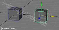
                Parenting is the most common function in Autodesk Maya that allows for one or more objects to follow another. When parenting, click the “child” or the object you want to follow and Shift select the “parent” or the object you want to lead then hit P. Now if you select the parent, it will always select the child. The child now follows the parent but its translation, rotation, and scale values do not change.

Steps to Parenting:

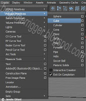
 Step 1: Make two or more objects. Go to the Create Tab à Polygon Primitives à whatever shape you want

Step 2: Hold the Shift button and select the child then the parent.

Step 3: Hit P.


Parent Constraint:


                A Parent Constraint differs from Parenting because Autodesk Maya creates a connection that actually affects the child object’s translation and rotation values, but the constraint does not influence the scale values at all. I refer to the parent object as the “driver” and the child object as the “driven.” A driven object can have more than one driver per connection, but you have to make multiple connections to have more than one driven per driver. The Parent Constraint gives you more control in other areas as well that will come in handy when you actually start setting up a rig, but this is a brief summary of how a Parent Constraint differs from a strait Parent.

Setting Up a Parent Constraint:
Step 1: Make two or more objects. Go to the Create Tab à Polygon Primitives à whatever shape you want 
                     

Step 2: Hold down the Shift button and select the driver then the driven.

Step 3: Go to the top, and make sure the Menu Bar setting is on Animation.

Step 4: Go to the Constraint Tab à Parent and the driven object should turn pink


*Look in the channel box; you will find the translation and rotation values for the driven object to be blue. Any time you see channel boxes highlighted with a color, it means that the object is being controlled by an other source. Sometimes the highlighted values cannot be changed, but others, like this parent constraint, will still allow you to change the driven object without affecting the constraint's effect.*


Reference

(2012).Maya's User's Guide: Create a Parent Constraint.http://download.autodesk.com/global/docs/maya2013/en_us/index.html?url=files/CSCo_Parent_constraint_workflow.htm,topicNumber=d30e296266
Slick, Justin.Maya Training Series1.3 Object Creation.N.D.http://3d.about.com/od/Creating-3D-The-CG-Pipeline/ss/Maya-Lesson-1-3-Object-Creation.htm

Friday, October 26, 2012

Getting Used to Autodesk Maya 2013 Part 2

Getting Used to Autodesk Maya 2013 Part 2

Autodesk Maya's Tools
      I will be discussing the different areas to find tools as well as a few tools. You will not use all of the tools that Autodesk Maya has to offer. You need to know where to find tools because not all of the tools are present when you start Autodesk Maya.

The Menu Bar and Status Bar

·         Both the Menu Bar and  the Status Bar tell you what setting that you have applied to your scene or the file you have open. The settings refer to which set of tools that you are looking for. There are too many to display at start.
      Some of the tabs on the Menu Bar can change depending on what setting you have Maya:
o   Animation: Tools for joints and deformers for making the model move and change in more believeable ways
o   Polygons: Tools for modeling object
o   Surfaces:  Tools to fine tune surfaces
o   Dynamics: Tools for special effects such as fire
o   Rendering: Tools for lighting and texturing
o   nDynamics: Tools for more complex special effects
·         The Status Bar tells you which mode you are selecting (this can also be accessed by right clicking in the workspace) or how you move the selected objects or components such as snapping to the grid. Both the Menu Bar and the Status Bar have the standard save, open, and new scene options, but the Status Bar has it represent graphically while the Menu Bar has it in the "File" drop down menu.

The Toolbox
           The Toolbox is on the left side of the workspace and contains some of the common tools needed and the very last box will show the last tool used.
       Here are the tools listed from top to bottom:
o   Selection Tool (use the Q button as a hotkey): The most basic way of selecting objects and components. It looks just like a normal cursor.
o   Lasso Tool: This selection tool looks like a lasso and will make a selection based on an area that you draw over.
o   Paint Selection Tool: Selects by using a brush directly on the object to select components. The brush radius can be changed by holding down B and moving the cursor while holding down the left mouse button.
o   Move Tool (use the W button as a hotkey): Translates objects or components on three axes and is graphically represented by 3 colored arrows that correspond with the axes found at the bottom of the workspace. The middle box will move the object in all three axes at the same time.
o   Rotate Tool (use the E button as a hotkey): Rotates objects or components on the three axes and is graphically represented with 3 circular handles corresponding with the axes found at the bottom of the workspace. The bigger handle around the three colored ones to rotates the object around all three at the same time.
o   Scale Tool (use the R button as a hotkey): Changes objects or components on the three axes and has boxes for handles that correspond with the three axes found at the bottom of the workspace. The middle box will make a uniform scale.
o   Universal Manipulator: Puts the Move Tool, Rotate Tool, and Scale Tool in one tool.
o   Soft Modification Tool: Lets you smoothly, uniformly modify a group of vertices (or points) on a mesh or object.
o   Show Manipulator Tool: Shows the hidden parts of certain objects like lights.

Thursday, October 25, 2012

Getting Used to Autodesk Maya 2013 Part 1


Getting Used to Autodesk Maya 2013 Part 1

The Window at a Glance
                The Autodesk Maya 2013 interface can at times be intimidating, but I will be taking it apart into easier understand pieces. These are the basic features that you need to know in order to continue. More parts will be introduced to you as the blog progresses.


The Workspace
          The workspace is the center window where you will spend the most time working. Your objects are visible in the workspace and can be manipulated in 4 panels:
   

  • Perspective (3D representation of an object)
  • Front (2D representation of an object)
  •   Side (2D representation of an object)
  •  Top (2D representation of an object)
         These panels can be toggled or switched by using the
space bar and hovering your cursor over the panel you want. To change from wireframe (just lines) to shaded (having color) switch between button 4 for wireframe and button 6 for shaded on your keyboard, and to change from smooth to normal or more straight edged, use button 1 for normal and button 3 for smooth on your keyboard.


The Channel Box
·         The Channel Box says the name of the object as well as displays the translate, rotate, and scale values of that object. You can change the name of the object from here or any of the values seen. The Channel Box gives you information like the shape node's name and history or past actions in the "INPUTS" area towards the bottom of the Channel Box.

*A node is a part of any object. Autodesk Maya automatically makes
three nodes per object: one for the dimensions, one shape node,
and one node for shading. You will not mess with these for some
time, but they are nice to know.*